Telescope Field of View Calculator

Telescope Field of View Calculator
A telescope field of view calculator shows how much sky an eyepiece or camera will cover. Visual observers can estimate true field from apparent field and magnification or calculate it from field-stop diameter. Camera users should use sensor dimensions and effective focal length. Drift timing can measure the assembled system, but none of these methods alone predicts vignetting, edge sharpness, or equipment compatibility.
Key Takeaways
- True field of view is the angular width of sky visible or recorded through the complete optical system.
- The field-stop method is generally the stronger calculated visual estimate when reliable field-stop data is available.
- Camera field of view depends on active sensor dimensions and effective focal length, not visual eyepiece magnification.
- Drift timing can measure an assembled system, but exact celestial-pole declinations are invalid and the crossing must pass close to the field center.
- A target needs framing margin; a calculated field equal to the target’s catalog size is usually too tight.
This guide explains how to choose the correct calculation method, interpret differences between results, plan visual and camera framing, and recognize limits that the calculator itself cannot measure.
Method disclosure: This guide uses published specifications, authoritative documentation, geometric relationships, and reproducible calculations. It does not claim hands-on product testing, laboratory measurement, or external technical review.
Telescope Field of View Calculator
Select the mode that matches the equipment at the focal plane. The calculator separates formula-based visual fields, camera sensor fields, and empirical drift measurements.
This guide—not the numerical output alone—explains why real-world framing can still be affected by distortion, spacing, vignetting, incomplete illumination, and edge performance.
Calculator Modes
| Calculator mode | Use it for | Principal inputs |
|---|---|---|
| Visual AFOV mode | A quick estimate of the circular sky field seen through an eyepiece | Telescope focal length, optical multiplier, eyepiece focal length, apparent field |
| Visual field-stop mode | A generally more reliable calculated visual field | Telescope focal length, optical multiplier, effective field-stop diameter |
| Camera sensor mode | The rectangular field recorded by a camera | Telescope focal length, optical multiplier, active sensor width and height |
| Drift measurement mode | An empirical field measurement from the assembled system | Drift time and star declination |
The methods are related, but their inputs are not interchangeable.
Calculator Inputs
| Input | Required? | What to enter | Example |
|---|---|---|---|
| Telescope focal length | Required for formula-based visual and camera fields; not required for drift measurement | Native telescope focal length in millimeters | 1,200 mm |
| Optical multiplier | Optional; defaults to 1 |
Factor applied by an installed reducer, corrector, extender, or Barlow | 0.8 |
| Eyepiece focal length | Required for AFOV-based visual field | Focal length printed on the eyepiece | 20 mm |
| Eyepiece apparent field | Required for AFOV-based visual field | Manufacturer-published AFOV in degrees | 68° |
| Effective field-stop diameter | Required for field-stop visual field | Manufacturer-published effective diameter in millimeters | 23 mm |
| Active sensor width | Required for horizontal camera field | Active imaging width in millimeters | 22.3 mm |
| Active sensor height | Required for vertical camera field | Active imaging height in millimeters | 14.9 mm |
| Star drift time | Required for drift-measured field | Edge-to-edge crossing time in seconds | 240 s |
| Star declination | Required for declination-corrected drift field | Signed declination strictly between −90° and +90° | −10° |
| Target angular width | Optional framing input | Intended target width in degrees or arcminutes | 1.0° |
| Target angular height | Optional framing input | Intended target height in degrees or arcminutes | 0.6° |
Which Inputs Does Each Output Require?
The following table is the authoritative input-dependency reference for this calculator.
| Output | Required inputs |
|---|---|
| Effective focal length | Telescope focal length, optical multiplier |
| Visual magnification | Telescope focal length, optical multiplier, eyepiece focal length |
| AFOV-based true-field estimate | Telescope focal length, optical multiplier, eyepiece focal length, apparent field |
| Field-stop-based true-field estimate | Telescope focal length, optical multiplier, effective field-stop diameter |
| Camera horizontal field | Telescope focal length, optical multiplier, active sensor width |
| Camera vertical field | Telescope focal length, optical multiplier, active sensor height |
| Camera diagonal field | Telescope focal length, optical multiplier, active sensor width, active sensor height |
| Drift-measured field | Drift time, star declination |
| Visual Field Fit Ratio | Visual true-field diameter and target angular diameter or intended framing width |
| Camera horizontal fit ratio | Camera horizontal field and target angular width projected onto the sensor’s horizontal axis |
| Camera vertical fit ratio | Camera vertical field and target angular height projected onto the sensor’s vertical axis |
Eyepiece focal length is not required for the field-stop formula when effective field-stop diameter and effective telescope focal length are already known.
Input Requirements
Use valid numerical values and the units shown.
Physical dimensions, focal lengths, optical multipliers, drift times, and target dimensions must be greater than zero.
Star declination is a signed angular coordinate. Negative declinations, positive declinations, and 0° are valid.
For drift measurement, declination must satisfy:
−90° < Declination < +90°
The exact celestial poles at −90° and +90° are invalid for this method because the sidereal drift component used by the formula becomes zero.
A star near 0° declination is preferred because it crosses the field more quickly and requires the smallest declination correction.
Use these entry rules:
- Enter focal lengths, field-stop diameter, and sensor dimensions in millimeters.
- Enter apparent field, declination, and target dimensions in degrees unless the calculator explicitly supports arcminutes.
- Enter
1when no accessory changes effective focal length. - Enter
2for a nominal 2× Barlow or focal extender. - Enter
0.8for a nominal 0.8× reducer. - Do not enter
80for a 0.8× reducer. - Use active sensor dimensions, not camera-body or sensor-package dimensions.
- When several eyepiece-specific values are entered, all must describe the same eyepiece.
- Unless an input accepts unit symbols, enter
20rather than20 mmand68rather than68°.
Each output is produced only when all inputs required for that calculation are present and valid. Optional or unrelated fields may remain blank.
If a physical dimension, focal length, multiplier, drift time, or target size is zero, negative, or nonnumeric, the dependent result is invalid.
Declination is handled separately:
- Negative declinations are valid.
0°declination is valid.- Declinations greater than
−90°and less than+90°are mathematically usable. - The exact values
−90°and+90°are invalid for drift measurement. - Stars close to either celestial pole are poor measurement targets because their drift is extremely slow.
Drift mode does not return a normal field measurement when cos(Declination) is zero. When the cosine is very small, the result includes a slow-drift warning and recommends a star closer to the celestial equator.
Review unusually large or small results for mixed units or misplaced decimal points before making an equipment decision.
Avoid Applying an Optical Multiplier Twice
This page uses:
Effective focal length
= Native telescope focal length × Optical multiplier
Enter either:
- The native telescope focal length and the installed accessory multiplier, or
- A directly measured effective focal length with the multiplier set to
1.
Do not enter a reduced or extended focal length and then apply the same multiplier again.
Optical Compatibility Is a Separate Question
An optical multiplier describes a focal-length change. It does not prove that an accessory is compatible with a telescope, focuser, diagonal, camera, eyepiece, or observing mode.
Some reducers and correctors are designed for particular telescope designs or primarily for imaging. Before treating a calculated configuration as an equipment option, verify:
- Supported telescope design
- Intended visual or imaging use
- Required working distance
- Back-focus requirement
- Available focuser travel
- Clear aperture
- Corrected image circle
- Diagonal or adapter compatibility
- Mechanical load
A mathematically valid field is not an automatic compatibility or purchase recommendation.
How Is Telescope Field of View Defined?
Telescope field of view is the angular extent of sky visible or recorded through the complete optical system.
Field of view is commonly expressed in degrees, arcminutes, or arcseconds:
1 degree = 60 arcminutes

1 arcminute = 60 arcseconds

1 degree = 3,600 arcseconds
A field of 1.5° equals:
1.5 × 60 = 90 arcminutes
NASA’s Daily Moon Guide explains angular diameter and reports the Moon’s changing apparent size in arcseconds.
How Do Apparent and True Field of View Differ?
Apparent field of view describes the perceived angular width of an eyepiece view. True field of view describes the actual angular width of sky shown by the eyepiece and telescope together.
| Term | Abbreviation | Meaning |
|---|---|---|
| Apparent field of view | AFOV | The apparent angular span of the eyepiece view |
| True field of view | TFOV | The actual angular span of sky visible through the complete visual system |
| Effective field stop | — | The eyepiece aperture that limits the visible angular field |
| Image circle | — | The focal-plane area over which the telescope forms an image |
| Fully illuminated field | — | The region receiving the intended illumination without substantial falloff |
| Usable field | — | The region with acceptable illumination and optical performance for the intended use |
A wider apparent field does not automatically show a wider area of sky. Telescope focal length and effective field-stop diameter also matter.
Which Field-of-View Method Should You Use?
Use the field-stop method when reliable effective field-stop data is available. Use AFOV divided by magnification for a quick estimate. Use sensor geometry for cameras. Use drift timing when you need an empirical check of the assembled system.
| Method | Best use | Main advantage | Main limitation |
|---|---|---|---|
| AFOV divided by magnification | Quick visual estimate | Uses commonly published eyepiece specifications | Sensitive to eyepiece distortion and rounded AFOV values |
| Field-stop formula | Visual eyepiece planning | Uses the aperture that directly constrains angular field | Requires trustworthy effective field-stop data |
| Sensor geometry | Camera framing | Provides horizontal, vertical, and diagonal coverage | Does not predict illumination or edge quality |
| Drift timing | Empirical visual or camera field measurement | Includes the assembled optical system | Sensitive to timing, centering, declination, and field orientation |
Field-Method Confidence Ladder
For visual planning, a useful order of preference is:
- A carefully performed central drift measurement
- A field-stop-based estimate using reliable manufacturer data
- An AFOV-based estimate
This hierarchy is an editorial planning framework, not an industry standard.
A carefully performed central drift can provide the strongest empirical check. A poorly centered or inconsistently timed drift may be less reliable than good manufacturer field-stop data.
What Formulas Does the Calculator Use?
Effective Telescope Focal Length
Effective focal length
= Native telescope focal length × Optical multiplier
For a 1,000 mm telescope with a nominal 0.8× reducer:
Effective focal length = 1,000 × 0.8
Effective focal length = 800 mm
For the same telescope with a nominal 2× Barlow:
Effective focal length = 1,000 × 2
Effective focal length = 2,000 mm
The result is nominal when actual reduction or amplification depends on spacing.
In moving-primary systems, including many Schmidt-Cassegrain telescopes, effective focal length can change as the primary mirror moves to accommodate a different back-focus distance. Celestron discusses this interaction in Understanding Focal Reducers.
The calculator uses the entered focal length and multiplier. It does not independently measure the assembled system’s effective focal length.
Visual Magnification
Magnification
= Effective telescope focal length ÷ Eyepiece focal length
For a 650 mm telescope with a 20 mm eyepiece:
Magnification = 650 ÷ 20
Magnification = 32.5×
Use the Telescope Magnification Calculator when magnification, exit pupil, and practical power ranges are the primary questions.
AFOV-Based True-Field Estimate
Estimated true field
≈ Eyepiece apparent field ÷ Magnification
For a 68° eyepiece operating at 32.5×:
Estimated true field = 68 ÷ 32.5
Estimated true field ≈ 2.09°
Celestron includes this relationship in its Astronomy Glossary of Terms.
This remains an estimate. Angular magnification distortion and rounded catalog specifications can cause the actual true field to differ from the simple division.
Field-Stop-Based True-Field Estimate
Estimated true field in degrees
≈ 57.3 × Effective field-stop diameter
÷ Effective telescope focal length
For a 23 mm effective field stop and a 650 mm telescope:
Estimated true field
= 57.3 × 23 ÷ 650
Estimated true field
≈ 2.03°
Tele Vue publishes this formula in its Eyepiece Technical Notes.
Use a manufacturer-published effective field-stop diameter. Do not substitute:
- Eyepiece barrel diameter
- Filter-thread diameter
- Eye-lens diameter
- Visible glass diameter
- Diagonal clear aperture
This formula estimates angular coverage, not illumination or edge quality. See the Three-Field Reality Check for practical limitations.
Geometric Camera Sensor Field of View
For a rectangular sensor under the usual rectilinear geometric model:
Horizontal field
= 2 × arctan(Sensor width ÷ (2 × Effective focal length))

Vertical field
= 2 × arctan(Sensor height ÷ (2 × Effective focal length))

Diagonal field
= 2 × arctan(Sensor diagonal ÷ (2 × Effective focal length))
Sensor diagonal is:
Sensor diagonal
= √(Sensor width² + Sensor height²)
The angular result must be converted from radians to degrees when the calculation system returns radians.
For relatively small angles, this approximation is convenient:
Field in degrees
≈ 57.3 × Sensor dimension
÷ Effective focal length
Celestron gives a related sensor-size approximation in its guide to Camera and Telescope Field of View.
The arctangent formulas are geometrically exact for the entered sensor dimensions and effective focal length under the assumed rectilinear projection.
The real recorded field may differ when:
- The optical system introduces distortion.
- The entered focal length is nominal rather than measured.
- Reducer spacing changes the effective focal length.
- The camera applies an undocumented crop.
- Calibration or stacking software removes border pixels.
Drift-Timing Field Measurement
At the celestial equator, the approximate sidereal drift rate is:
15 arcseconds per second of time
Therefore:
True field in degrees
≈ Drift time in seconds × 15 × cos(Declination)
÷ 3,600
This simplifies to:
True field in degrees
≈ Drift time in seconds × cos(Declination)
÷ 240
The divisor 240 is a convenient rounded approximation rather than a laboratory calibration constant. A more precise calculation can use the sidereal day of approximately 86,164 seconds.
Celestron describes the approximately 15-arcseconds-per-second drift rate near the celestial equator in its Drift Method for True Field. The University of Nevada, Las Vegas field-of-view illustration shows why crossing time increases with the absolute value of declination.
A four-minute crossing at 0° declination gives:
240 × cos(0°) ÷ 240 = 1.00°
The exact poles cannot produce a valid drift field:
cos(−90°) = 0
cos(+90°) = 0
Drift-mode input behavior should therefore be:
Declination = −90.0° → Invalid for drift measurement
Declination = −89.9° → Valid with slow-drift warning
Declination = 0.0°   → Valid and preferred
Declination = +89.9° → Valid with slow-drift warning
Declination = +90.0° → Invalid for drift measurement
If cos(Declination) is zero, the drift method cannot produce a valid field measurement.
When cos(Declination) is very small, the crossing becomes unusually slow and practical timing errors become more important. In that case, select a star closer to the celestial equator.
For a useful measurement:
- Disable tracking.
- Choose a star near the celestial equator.
- Place the star just outside one edge of the field.
- Let the star cross close to the field center.
- Time the complete edge-to-edge crossing.
- Repeat the measurement several times.
- Average the results.
- Apply the declination correction.
For a circular visual field, an off-center path measures a shorter chord rather than the full field diameter.
For a rectangular camera field, drift timing measures the field dimension along the drift direction. It does not automatically measure the sensor diagonal.
Do not use the Sun for drift timing.
Drift-Mode Warnings
When the entered declination produces a very slow crossing, the result should display:
High-declination warning: This star will drift very slowly across the field. A star closer to the celestial equator will normally produce a faster and more reliable measurement.
The result should also remind the user:
Measurement warning: The drift formula assumes an edge-to-edge crossing close to the field center. In a circular field, an off-center path measures a shorter chord and underestimates the full field diameter.
How Are Calculation Precision and Rounding Handled?
The calculator performs fit comparisons and category assignment using unrounded numerical values. Rounding is applied only when results are displayed.
Display precision:
- Effective focal length: nearest whole millimeter, or one decimal place when needed
- Magnification: one decimal place
- Visual field of view: two decimal places
- Camera horizontal, vertical, and diagonal fields: two decimal places
- Drift-measured field: two decimal places
- Field Fit Ratio: two decimal places
The calculation order is:
1. Calculate the full-precision value.
2. Compare or classify the full-precision value.
3. Round the value for display.
A rounded result may appear equal to a boundary even when the unrounded value falls slightly above or below it.
What Is the Field Fit Ratio?
The Field Fit Ratio compares an available field dimension with the target dimension that must fit inside it.
Field Fit Ratio
= Available field dimension ÷ Target angular dimension
The Field Fit Ratio is an original editorial planning framework. It is not an industry standard, an image-quality grade, or a universal aesthetic rule.
| Field Fit Ratio | Framing interpretation |
|---|---|
< 1.00 |
Full target does not fit geometrically |
1.00 to < 1.20 |
Very tight framing with little tolerance |
1.20 to < 1.60 |
Moderate framing margin |
1.60 to < 2.50 |
Wider contextual framing |
≥ 2.50 |
Broad context or finding field |
The interpretation bands are planning heuristics rather than measured universal preferences.
Visual Field Fit Ratio
For a roughly circular visual target:
Visual Field Fit Ratio
= Visual true-field diameter
÷ Target angular diameter or intended framing width
A 1.25° field framing a 0.50° Moon gives:
1.25 ÷ 0.50 = 2.50
The Moon occupies about 40% of the field diameter.
Camera Fit Ratios
For a rectangular camera sensor:
Horizontal Fit Ratio
= Camera horizontal field ÷ Target width projected onto the horizontal sensor axis

Vertical Fit Ratio
= Camera vertical field ÷ Target height projected onto the vertical sensor axis
The smaller ratio controls whether the target fits at the selected orientation.
The ratio is a one-dimensional framing aid, not a complete geometric fit test. For irregular, elongated, or rotated targets, use the target dimensions projected onto the camera’s current horizontal and vertical axes.
Camera rotation does not change the sensor’s physical width, height, or diagonal. It can change how those dimensions project onto an elongated target and may therefore improve the fit.
After rotating the camera, recalculate or reproject the target width and height relative to the new sensor axes. Do not continue using the horizontal and vertical fit ratios calculated for the previous orientation.
Which Target Size Should You Use?
Use the angular extent relevant to the intended observation.
A catalog diameter may describe:
- A bright central region
- A particular wavelength
- A specified surface-brightness threshold
- A photographic extent different from the visual extent
For long-exposure imaging, use the extent you actually want to record, not automatically the smallest catalog dimension.
NASA notes that the Andromeda Galaxy spans about six times the apparent diameter of the full Moon in its Messier 31 guide. A shallow visual observation may show a smaller bright region, while a long exposure can record a much larger faint disk.
Field Fit Ratio Boundary Handling
Field Fit Ratio categories use the unrounded ratio.
For example:
Unrounded ratio: 1.196
Displayed ratio: 1.20
Category: Very tight framing
The category remains based on 1.196, even though the displayed value rounds to 1.20.
The Three-Field Reality Check
A field calculation answers only the first of three practical questions.
1. Calculated Angular Field
The geometric sky coverage predicted by apparent field, field stop, sensor size, or drift time.
2. Fully Illuminated Field
The region that receives sufficient illumination.
A baffle, focuser drawtube, diagonal, adapter, reducer, filter, or narrow mechanical opening can dim the outer field.
3. Usable Optical Field
The region that remains sufficiently sharp and well illuminated for the intended observation or image.
The usable field may be reduced by:
- Coma
- Field curvature
- Astigmatism
- Chromatic aberration
- Reducer or flattener spacing error
- Sensor tilt
- Vignetting
- Eyepiece distortion
- Eye-position limitations
The Three-Field Reality Check is an explanatory framework, not an instrument measurement or industry standard.
What Can the Calculator Not Determine?
The calculator can derive angular relationships from entered dimensions, focal length, apparent field, field stop, or drift time.
It cannot directly measure:
- Optical distortion
- Fully illuminated field diameter
- Vignetting severity
- Edge sharpness
- Off-axis aberrations
- Sensor tilt
- Corrector-spacing accuracy
- Eye-position comfort
- Accessory compatibility
- The faint outer extent a particular exposure will record
A warning about these limits is not the same as detecting or quantifying them.
How Do You Use the Calculator?
For Visual AFOV Mode
- Enter the telescope’s native focal length.
- Enter the installed optical multiplier.
- Enter the eyepiece focal length.
- Enter the eyepiece apparent field.
- Review magnification and the AFOV-based field estimate.
- Compare the field with the target’s angular size.
- Check exit pupil before choosing the eyepiece.
For Visual Field-Stop Mode
- Enter the telescope’s native focal length.
- Enter the installed optical multiplier.
- Enter the manufacturer-published effective field-stop diameter.
- Calculate the field-stop-based field.
- Compare the result with any AFOV estimate.
- Use the field-stop result for framing when its source data is reliable.
For Camera Imaging
- Enter the telescope’s native focal length.
- Enter the installed reducer, corrector, extender, or Barlow factor.
- Confirm the resulting effective focal length.
- Enter the active sensor width and height.
- Calculate horizontal, vertical, and diagonal fields with the arctangent formulas.
- Enter the target’s intended angular dimensions.
- Compare horizontal and vertical fit ratios.
- Test the intended sensor orientation.
- Reproject the target dimensions after changing camera rotation.
- Allow margin for dithering, registration, stacking, and cropping.
- Verify reducer or flattener spacing before relying on edge performance.
When entering a directly measured effective focal length, set the multiplier to 1.
For Drift Measurement
- Select a star close to
0°declination. - Enter the signed declination.
- Confirm that the value is strictly greater than
−90°and less than+90°. - Disable tracking.
- Arrange a central crossing.
- Time the complete crossing.
- Repeat the timing several times.
- Average the measurements.
- Compare the empirical result with the formula estimates.
Which Is Better: AFOV or Field-Stop Calculation?
The field-stop method is generally better for visual framing when reliable effective field-stop data is available. The AFOV method remains useful when field-stop data is unavailable.
| Consideration | AFOV method | Field-stop method |
|---|---|---|
| Requires eyepiece focal length | Yes | No |
| Requires magnification | Yes | No |
| Requires field-stop data | No | Yes |
| More affected by apparent-field distortion | Yes | Less |
| Useful for quick comparison | Yes | Yes |
| Preferred for close framing | Secondary method | Usually preferred |
A substantial disagreement should trigger an input review.
Possible causes include:
- Rounded or nominal AFOV
- Incorrect field-stop diameter
- Specifications taken from different eyepieces
- Incorrect telescope focal length
- Unaccounted reducer or Barlow
- Moving-primary telescope operating away from nominal focal length
- Eyepiece distortion
Do not average conflicting results before checking the inputs.
Does a Wider Apparent Field Always Show More Sky?
No. A wider apparent field can provide nearly the same true field at higher magnification rather than a larger angular field.
The following values are hypothetical and demonstrate the relationship rather than compare specific commercial products.
| Eyepiece | Apparent field | Magnification in a 1,200 mm telescope | AFOV-based field |
|---|---|---|---|
| 32 mm | 62° | 37.5× | 1.65° |
| 20 mm | 100° | 60× | 1.67° |
The fields are similar, but the experience differs.
The 20 mm eyepiece provides:
- Higher magnification
- A smaller exit pupil
- A more expansive apparent presentation
- A darker apparent sky background
The 32 mm eyepiece provides:
- Lower magnification
- A larger exit pupil
- Potentially brighter extended objects
- A less expansive apparent presentation
Neither is universally better. Target size, surface brightness, eye relief, optical correction, sky conditions, and observer preference all matter.
Worked Example: Visual Field by Two Methods
Consider:
- Telescope focal length: 650 mm
- Optical multiplier: 1×
- Eyepiece focal length: 20 mm
- Apparent field: 68°
- Effective field stop: 23 mm
Step 1: Calculate Magnification
Magnification = 650 ÷ 20
Magnification = 32.5×
Step 2: Calculate the AFOV-Based Field
True field ≈ 68 ÷ 32.5
True field ≈ 2.09°
Step 3: Calculate the Field-Stop-Based Field
True field ≈ 57.3 × 23 ÷ 650
True field ≈ 2.03°
Step 4: Compare the Results
Difference = 2.09° − 2.03°
Difference = 0.06°
Relative to the field-stop result:
0.06 ÷ 2.03 × 100
≈ 3%
The difference does not automatically indicate an error. When the effective field-stop value is reliable, the 2.03° result is generally the stronger framing estimate.
Worked Example: Camera Field of View
Consider:
- Native telescope focal length: 750 mm
- Optical multiplier: 0.8×
- Active sensor width: 22.3 mm
- Active sensor height: 14.9 mm
Step 1: Calculate Effective Focal Length
Effective focal length = 750 × 0.8
Effective focal length = 600 mm
Step 2: Calculate Sensor Diagonal
Sensor diagonal
= √(22.3² + 14.9²)
≈ 26.82 mm
Step 3: Calculate Camera Fields
Horizontal field
= 2 × arctan(22.3 ÷ 1,200)
≈ 2.13°

Vertical field
= 2 × arctan(14.9 ÷ 1,200)
≈ 1.42°

Diagonal field
= 2 × arctan(26.82 ÷ 1,200)
≈ 2.56°
The rectangular camera field is approximately:
2.13° × 1.42°
A full Moon, whose apparent diameter is roughly half a degree, fits with substantial margin.
A target with a faint extent near 3° × 1° would not fit horizontally at this orientation, even though its brighter central region might.
Possible responses include:
- Rotate the camera and recalculate the projected target dimensions.
- Use a shorter effective focal length.
- Use a larger sensor.
- Accept a crop of the faint outer region.
- Build a mosaic.
Derived Field-Stop Reference Data
The table below is derived from:
True field
≈ 57.3 × Field stop ÷ Telescope focal length
It is calculated reference data, not a measurement of specific eyepieces or telescopes.
| Effective telescope focal length | 10 mm field stop | 20 mm | 27 mm | 35 mm | 46 mm |
|---|---|---|---|---|---|
| 400 mm | 1.43° | 2.87° | 3.87° | 5.01° | 6.59° |
| 650 mm | 0.88° | 1.76° | 2.38° | 3.09° | 4.06° |
| 1,000 mm | 0.57° | 1.15° | 1.55° | 2.01° | 2.64° |
| 1,200 mm | 0.48° | 0.95° | 1.29° | 1.67° | 2.20° |
| 2,000 mm | 0.29° | 0.57° | 0.77° | 1.00° | 1.32° |
For a fixed field stop, the small-angle estimate decreases approximately in inverse proportion to effective focal length.
The table does not establish that every field stop is compatible with every telescope, barrel size, diagonal, focuser, or baffle system.
How Do Barlows and Reducers Change Field of View?
A Barlow or focal extender narrows the calculated field by increasing effective focal length. A reducer widens the calculated field by decreasing effective focal length.
For a telescope with a 1,000 mm native focal length:
| Accessory | Effective focal length | Relative calculated field |
|---|---|---|
| No multiplier | 1,000 mm | 1.00× reference |
| 0.8× reducer | 800 mm | Approximately 1.25× wider |
| 0.63× reducer | 630 mm | Approximately 1.59× wider |
| 2× Barlow | 2,000 mm | Approximately half as wide |
| 3× Barlow | 3,000 mm | Approximately one-third as wide |
These relative values use the small-angle approximation, under which field of view is nearly inversely proportional to effective focal length when the limiting field-stop or sensor dimension remains fixed.
For most telescope fields, this provides a close planning estimate. When using the arctangent camera formula, recalculate the horizontal, vertical, and diagonal fields from the new effective focal length rather than assuming that every field dimension changes by exactly 1 ÷ multiplier.
The relative values in the table are rounded planning ratios. They are not substitutes for recalculating camera field of view with the full arctangent formula.
Actual results can also differ when spacing changes accessory strength or when a moving-primary telescope operates away from its nominal focal length.
How Do Visual and Camera Fields Differ?
Visual and camera field of view require different models.
| Characteristic | Visual eyepiece field | Camera sensor field |
|---|---|---|
| Typical shape | Circular | Rectangular |
| Main limiting dimension | Effective eyepiece field stop | Active sensor width and height |
| Uses eyepiece magnification | Yes for AFOV method | No |
| Uses apparent field | Sometimes | No |
| Uses sensor dimensions | No | Yes |
| Rotation changes framing | Usually unimportant | Often important |
| Eye position affects visible edge | Yes | No |
| Back-focus spacing affects results | Sometimes | Frequently |
A camera attached at prime focus does not have a useful visual-style eyepiece magnification. Describe the imaging system with effective focal length, sensor dimensions, image scale, and angular field.
What Limits the Widest Usable Field?
Eyepiece Field Stop
The field stop limits visual angular coverage.
Focuser and Barrel Size
A narrow opening may constrain a large field stop or light cone.
Telescope Baffles
Internal baffles can reduce off-axis illumination, particularly in compact compound telescopes.
Diagonal Clear Aperture
A diagonal may vignette a wide-field eyepiece if its internal opening is too small.
Reducer or Corrector Compatibility
Incorrect spacing can change focal length, increase aberrations, or prevent focus.
Camera Image Circle
A larger sensor records a wider field only when the telescope delivers a sufficiently large corrected and illuminated image circle.
Observer Eye Position
Insufficient eye relief or incorrect eye position can prevent the observer from seeing the full apparent field.
Optical Performance
The calculated field can include regions affected by coma, field curvature, astigmatism, chromatic aberration, or poor corrector spacing.
Common Telescope Field-of-View Mistakes
Confusing Apparent Field With True Field
A 100° eyepiece does not show 100° of sky.
Applying a Reducer Twice
Do not enter a reduced focal length and then apply the reducer factor again.
Using Native Focal Length After Adding an Accessory
A reducer, corrector, extender, or Barlow may change effective focal length.
Treating a Nominal Multiplier as a Measurement
Accessory strength can vary with spacing.
Using Barrel Diameter as Field-Stop Diameter
A 1.25-inch or 2-inch barrel size is not the effective field stop.
Combining Different Eyepiece Specifications
Focal length, apparent field, and field stop must describe the same eyepiece when used together.
Using Camera Crop Factor
Use physical active sensor dimensions rather than a photography crop-factor label.
Rejecting Negative Declination
Southern celestial declinations are valid inputs.
Accepting Exact Pole Declinations
The values −90° and +90° are invalid for drift measurement because the usable drift component is zero.
Measuring an Off-Center Drift
An off-center crossing measures a shorter chord through a circular field.
Assuming a Target Fits at a Ratio of Exactly 1.00
A ratio of 1.00 provides no practical margin.
Reusing Fit Ratios After Camera Rotation
Rotation changes the target’s projection onto the sensor axes. Recalculate the horizontal and vertical target dimensions after changing orientation.
Treating Calculated Field as Fully Illuminated Field
Geometric coverage does not guarantee uniform brightness or edge quality.
Treating Inverse Scaling as Exact for Camera Fields
The 1 ÷ multiplier relationship is a small-angle planning approximation. Use the full arctangent formula for camera-field recalculation.
Telescope Field-of-View Troubleshooting
| Symptom | Likely cause | Practical response |
|---|---|---|
| Target does not fit although the calculation says it should | No margin, wrong target extent, wrong focal length, or incorrect orientation | Recheck target dimensions and Field Fit Ratios |
| AFOV and field-stop estimates disagree | Distortion, rounded specifications, or incorrect field-stop data | Verify inputs and prefer reliable field-stop data |
| Outer visual field is dark | Vignetting, eye-position error, or restricted clear aperture | Check eye relief, diagonal, adapters, and baffles |
| Stars are poor near the edge | Coma, field curvature, astigmatism, spacing error, or eyepiece limitation | Verify correction and spacing; compare center and edge focus |
| Camera field is narrower than expected | Effective focal length is longer than entered | Check back focus, reducer spacing, and moving-primary geometry |
| Camera field is wider than expected | Effective focal length is shorter than entered | Confirm reducer factor or derive focal length from plate scale |
| Camera field after a multiplier change differs from a simple ratio | Arctangent geometry or optical distortion | Recalculate each sensor axis with the full camera formula |
| Only part of the sensor is illuminated | Image circle or clear aperture is too small | Review image-circle and accessory specifications |
| Full eyepiece field is difficult to see | Eye relief or eye position is unsuitable | Adjust the eyecup and viewing distance |
| Drift result varies between attempts | Crossing path or timing is inconsistent | Use central crossings and average several measurements |
| Drift mode returns no field at ±90° | Exact celestial pole selected | Choose a star with declination strictly between −90° and +90° |
| Drift result is extremely slow | Star is too close to a celestial pole | Choose a star nearer 0° declination |
| Large nebula remains incomplete | Faint extent exceeds one field | Use shorter focal length, a reducer, binoculars, or a mosaic |
| Reducer combination will not focus | Incorrect spacing or insufficient travel | Follow manufacturer back-focus guidance |
Field-of-View Planning Checklist
Before choosing an eyepiece or camera configuration:
- Confirm the telescope’s native focal length.
- Include every reducer, corrector, extender, or Barlow once.
- Use eyepiece specifications from the same eyepiece.
- Prefer manufacturer-published effective field-stop data.
- Use active sensor dimensions.
- Calculate horizontal and vertical camera fields separately.
- Recalculate camera fields after changing effective focal length.
- Reproject target dimensions after changing camera rotation.
- Use the target extent relevant to the intended observation.
- Add framing margin.
- Allow room for dithering, stacking alignment, and cropping.
- Use a drift star strictly between −90° and +90° declination.
- Prefer a drift star near the celestial equator.
- Arrange a central edge-to-edge crossing.
- Check diagonal, adapter, focuser, and reducer clear apertures.
- Verify the telescope’s corrected image circle.
- Confirm back-focus and spacing requirements.
- Compare field of view with magnification and exit pupil.
- Treat calculated, illuminated, and usable fields as separate concepts.
Related tools:
- Telescope Magnification Calculator
- Telescope Eyepiece Calculator
- Telescope Exit Pupil Calculator
- Telescope Focal Length Calculator
- Telescope Resolution Calculator
Essential Solar Observing Safety
Never look at the Sun through an unfiltered telescope, finder, binocular, camera lens, or other magnifying optical instrument. Severe and permanent eye injury can occur rapidly.
A field-of-view calculation does not make solar observation safe.
For direct telescopic solar viewing, use a special-purpose solar filter designed for the instrument and securely mounted over the front aperture.
The American Astronomical Society’s solar-filter guidance warns that:
- Finderscopes must be capped, removed, or safely filtered.
- Eyepiece-threaded solar filters are dangerous.
- Eclipse glasses do not make an unfiltered telescope safe.
- A front-mounted filter must be secured against accidental removal.
Ordinary sunglasses, smoked glass, photographic filters, exposed film, and improvised materials are not safe substitutes.
Inspect the filter before every use and follow the manufacturers’ instructions.
Practical Recommendations
- New visual observers: Begin with the AFOV estimate, then use reliable field-stop data when available.
- Wide-field observers: Compare field stops and effective focal lengths rather than apparent field alone.
- Planetary observers: A wider true field can reduce recentering even when the target is small.
- Deep-sky observers: Compare true field with exit pupil and the target’s faint outer extent.
- Astrophotographers: Calculate both sensor axes with the arctangent formula and reserve margin for rotation, dithering, registration, and cropping.
- Drift-measurement users: Choose a star near
0°declination and reject exact pole values. - Equipment buyers: Treat a calculated field as planning information, not proof of compatibility or edge performance.
Conclusion
This calculator separates the main ways of determining telescope field of view, while the guide explains how to interpret each result.
For visual use, reliable field-stop data generally provides the strongest calculated estimate. AFOV divided by magnification remains useful for quick planning. Camera systems require active sensor geometry and should be recalculated with the arctangent formula after focal-length changes. A carefully centered drift can empirically check the assembled field, provided the star is not at a celestial pole.
The best configuration frames the intended target with adequate margin and an acceptable usable field.
Frequently Asked Questions
Is apparent field of view the same as true field of view?
No. Apparent field describes the perceived width of an eyepiece view. True field describes the actual angular width of sky visible through the eyepiece and telescope together.
Which visual field-of-view formula should I use?
Use the field-stop formula when a trustworthy effective field-stop diameter is available. Use AFOV divided by magnification when field-stop data is unavailable.
Can I calculate visual field without eyepiece focal length?
Yes. The field-stop formula requires effective field-stop diameter and effective telescope focal length, not eyepiece focal length.
Can star declination be negative in a drift calculation?
Yes. Negative declinations and 0° are valid. Drift-mode declination must be strictly greater than −90° and less than +90°.
Does a 2× Barlow halve the true field?
Approximately, under the small-angle model and when the Barlow operates at its intended spacing. For a camera, recalculate each field dimension with the full arctangent formula rather than assuming an exact one-half result.
Why does a target not fit when its catalog size is smaller than the field?
The catalog size may describe only a bright core or one wavelength. The setup may also lack framing margin, use a different effective focal length, or lose usable area to rotation, vignetting, or cropping.
Sources
Scientific, Academic, and Safety References
NASA Science — Daily Moon Guide
Angular diameter and the relationship between degrees, arcminutes, and arcseconds. Accessed July 30, 2026.NASA Science — Messier 31, the Andromeda Galaxy
Reference for the large apparent angular extent of the Andromeda Galaxy. Accessed July 30, 2026.University of Nevada, Las Vegas — Field of View and Declination
Illustration of why drift crossing time increases with the absolute value of declination. Accessed July 30, 2026.University of Nebraska–Lincoln — Sidereal Time
Explanation of the sidereal day used for more precise drift-rate calculations. Accessed July 30, 2026.American Astronomical Society — Solar Filters for Optical Instruments
Safety requirements for front-aperture filters, finderscopes, and unfiltered optical devices. Accessed July 30, 2026.
Manufacturer Technical References
Tele Vue — Eyepiece Technical Notes
Effective field-stop terminology and the field-stop true-field formula. Accessed July 30, 2026.Tele Vue — Eyepiece Reference Data
Technical data concerning field stops, exit pupils, and eyepiece selection. Accessed July 30, 2026.Celestron — Astronomy Glossary of Terms
Definitions and the AFOV-based visual field estimate. Accessed July 30, 2026.Celestron — Camera and Telescope Field of View
Sensor-size and focal-length field approximation. Accessed July 30, 2026.Celestron — Understanding Focal Reducers
Reducer spacing, moving-primary focusing, back focus, and effective focal-length changes in Schmidt-Cassegrain systems. Accessed July 30, 2026.Celestron — Understanding Telescope Back Focus
Focal-plane location, spacing, focus travel, and accessory compatibility. Accessed July 30, 2026.Celestron — Drift Method for True Field
Approximate 15-arcseconds-per-second drift relationship near the celestial equator. Accessed July 30, 2026.
Manufacturer references are used for accessory behavior, field-stop terminology, camera geometry, and published calculation methods. They are not presented as substitutes for independent compatibility checks or institutional safety guidance.
More from Telescope & Optics Tools
Eyepiece Comparison Calculator
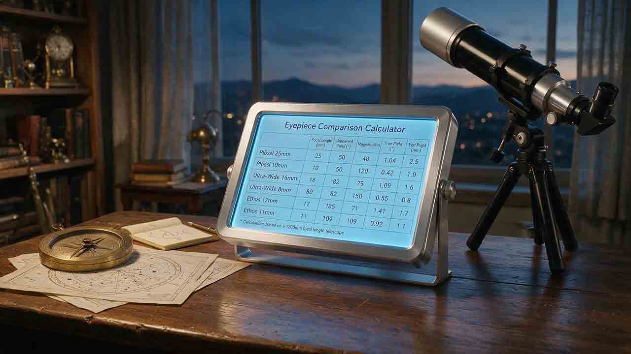
This guide explains how to compare up to four telescope eyepieces using magnification, exit pupil, true field, sky coverage, eye relief, weight, and observer-pupil matching. It defines a reference-eyepiece method so every ratio and percentage has a clear direction, prioritizes field-stop-based true field when reliable data is available, and warns when AFOV and field-stop estimates differ or when mixed calculation methods are used. The article adds the original Four-Dimension Eyepiece Role Map, a reproducible same-field-stop example, pupil-adjusted brightness calculations, weight conversion rules, compatibility reminders, and a transparent field-method warning threshold. Readers can identify meaningful role differences, evaluate possible overlap, and understand what calculations cannot reveal, including optical quality, comfort, mechanical safety, and real-world compatibility. The guidance is based on published specifications and authoritative references rather than product testing or universal rankings.
Telescope Resolution and Dawes Limit Calculator
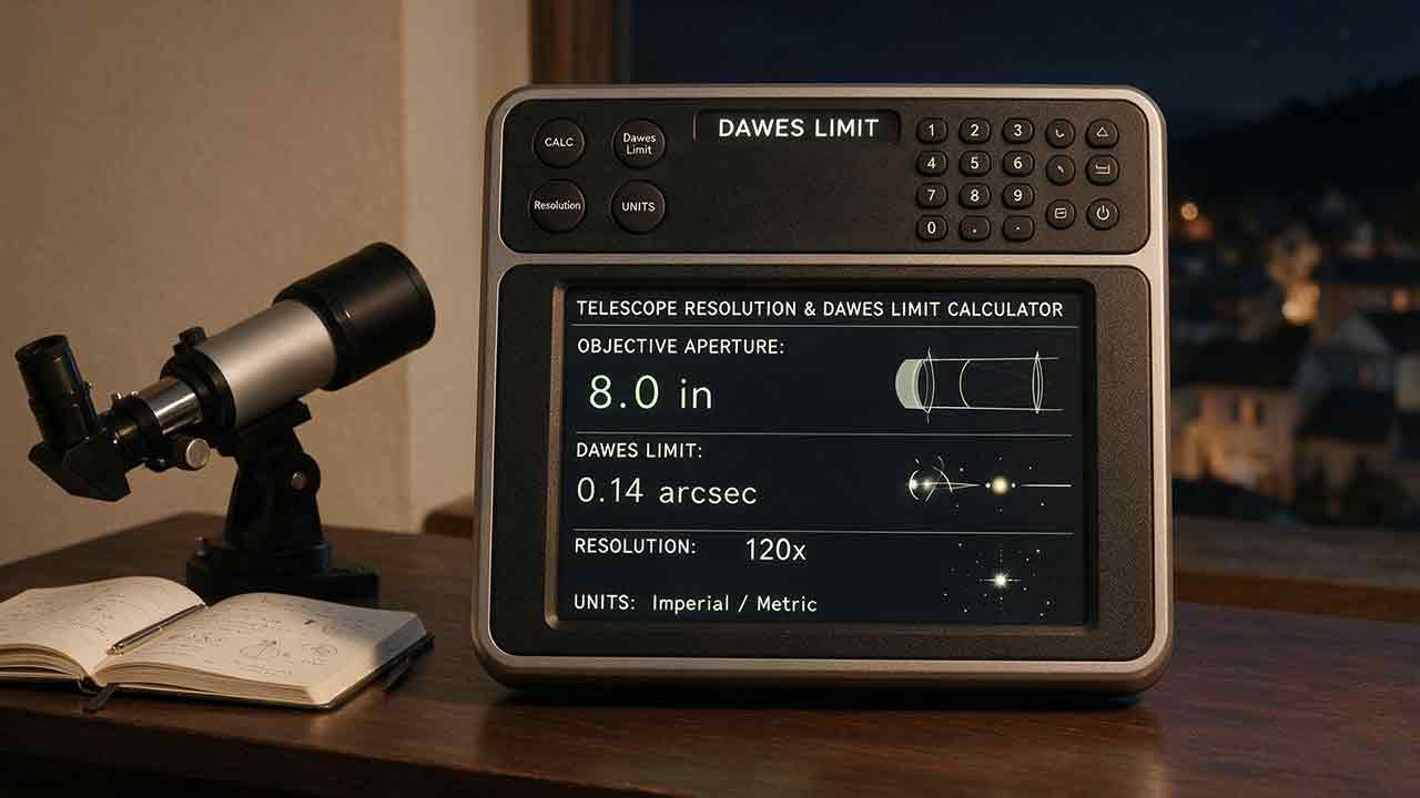
This guide explains how to calculate and interpret telescope resolution using Dawes’ limit and the Rayleigh criterion. It separates empirical visual double-star thresholds from wavelength-dependent diffraction, clarifies why the Rayleigh angle and Airy first-minimum radius share the same numerical value in the ideal circular-aperture model, and shows how aperture, wavelength, seeing, central obstruction, magnification, pixel scale, and target contrast affect practical results. Readers can compare double-star separation with both criteria, convert inches to millimeters safely, evaluate seeing with a published ratio, translate angular values into reference linear scales, and use upward rounding for required-aperture thresholds. Original tools such as the Resolution Reality Stack and separately named separation ratios help prevent theoretical limits from being mistaken for guaranteed observing or imaging performance. The article also includes worked examples, derived aperture data, troubleshooting guidance, solar-observing safety, and clearly documented calculation assumptions.
Telescope Exit Pupil Calculator
This guide explains how to calculate telescope exit pupil from either aperture and magnification or eyepiece focal length and effective focal ratio. It separates manual and specification-derived magnification paths, publishes an unrounded consistency tolerance, and shows how to interpret disagreements without silently replacing or averaging inputs. Readers can compare practical exit-pupil ranges, estimate pupil-limited outer aperture, understand the limits of unobstructed light-fraction calculations, and account for central obstruction and observer-pupil uncertainty. Original planning tools include the Same-Pupil Comparison Rule, the Pupil Match Audit, boundary-handling rules, a focal-ratio reference table, and a sensitivity table for oversized exit pupils. Worked examples, troubleshooting guidance, equipment checks, and solar-observing safety notes help observers choose eyepieces while avoiding exaggerated claims about resolution, brightness, compatibility, or useful magnification.
Explore More Topics
Astrophotography Storage Calculator
This guide explains how to estimate storage for astrophotography capture, processing, and backup without relying on misleading megapixel shortcuts. It compares measured-file, uncompressed-array, and bitrate methods; distinguishes mean, median, high-percentile, and maximum file-size statistics; and explains decimal versus binary storage units. Readers learn how FITS headers, padding, HDUs, RAW compression, calibration frames, RGB conversion, drizzle, mosaics, caches, and temporary files affect project size. Original planning tools include the Four-Bucket Storage Ledger, the Capture–Process–Protect Check, and a clearly defined storage expansion ratio. Worked examples show how to calculate peak logical data, project-relative headroom, complete-copy footprint, media count, write rate, and transfer time. The article also covers integrity verification, backup limitations, retention decisions, and troubleshooting. It is designed to help astrophotographers build realistic capacity plans for single sessions, multi-night projects, planetary video, star trails, and long-term archives.
Star Trail Exposure Calculator
This guide explains how to calculate star-trail exposure time from Earth’s sidereal rotation, stellar declination, and local image scale. It distinguishes polar sweep, declination-adjusted sky-path length, projected pixel length, recorded sweep, missing sweep, and the full start-to-end span of a stacked sequence. Original tables compare trail lengths at several declinations, quantify one-second frame gaps at different image scales, and show how recorded time, gap time, duty cycle, and sequence sweep relate. The Trail–Frame–Sequence Check provides a practical framework for separating celestial geometry, per-frame reliability, and sequence continuity. Worked examples also address the celestial-pole edge case, local WCS-based pixel movement, frame-count limits, long-exposure noise reduction, and the difference between a single exposure and stacked frames. Readers can use the article to plan smoother trails, avoid misleading sequence calculations, and verify expected motion with native-resolution test images.
Camera Field of View Calculator
This guide explains how to calculate horizontal, vertical, and diagonal camera field of view from the recorded active sensor dimensions and effective focal length. It distinguishes physical focal length from crop-factor comparisons, shows why aspect ratio and target rotation affect framing, and provides independently calculated reference tables for common sensor sizes and focal lengths. The original Frame Envelope Check separates ideal frame geometry, the target envelope, and the usable frame retained after dithering, registration, distortion correction, and cropping. Worked examples demonstrate target occupancy, maximum permitted focal length, rotated bounding boxes, and mosaic panel counts with overlap. The article also explains radians versus degrees, crop and stabilization modes, focus breathing, rectilinear versus fisheye projection, and plate-solving verification through a celestial WCS. Readers can use the formulas, margin budget, troubleshooting table, and framing checklist to plan wide-field compositions, small-target imaging, or mosaics without treating a mathematical edge-to-edge fit as a guaranteed final frame.